Search the Community
Showing results for tags 'English'.
Found 24 results
-

How to Control VFD with PLC using Ladder Logic?
caixiaofeng posted A plc and hmi english article in PLC programming learning
This is a complete tutorial about PLC ladder logic to control variable frequency drive (VFD) for motor speed control with speed selection from Field Local Panel or SCADA graphics. Execution Steps : Prepare a Control and Power drawing Commissioning and Parameters Programming in VFD Prepare a PLC program Prepare a SCADA design How to Control VFD with PLC ? Control and Power Diagram Commissioning and Parameters Programming in VFD Commissioning is needed for the proper function of VFD. Necessary parameter like Motor Nameplate details, Input Voltage, Motor Type, Frequency should be entered in VFD during quick commissioning. After successful quick commissioning, now it’s a time to install the advanced commissioning. This commissioning is needed to give the details of all the digital and analog inputs and outputs, like Information about Digital inputs of Start command and Speed Selection command Information about Digital Outputs like Status of Drive Running and Drive in Fault etc. Information about Analog Inputs like Speed Input 1 and Speed Input 2 Information about Analog Outputs like Current and Frequency of Motor PLC Program Network 1 : In this Network 1, we are checking whether the VFD is ready to start. This signal will come when all the conditions are healthy as well as safety and power feedbacks are active. Network 2 : In the Network 2, When start button is pressed, VFD Drive_DO bit will be set, if Ready_to_Start and No Error will be there. Network 3 : This is the stop logic, When stop button is pressed it will reset the Drive_DO bit. Network 4 : In this Network 4, this logic is required for safety as soon as Drive_DO bit will set and if any case VFD will not operate due to any fault then after predefined wait time, here we considered it as Run_FB_Time, it will reset the Drive_DO bit and generate Error. This Error you can acknowledge from the SCADA after resolving the error from the field side. Network 5 : In this Network 5, If the VFD is taking more current and gives overload error, then it will reset Drive_DO bit and generate Error. This Error you can acknowledge from the SCADA after resolving the error from the field side. Network 6 : This is the speed selection Digital output, if you select speed input as a local then it will not activate Speed Selection bit resulting Speed_DO absent and if you select speed input as a remote then it will activate Speed Selection bit resulting Speed_DO present. SCADA Design Normal State This is the normal state of motor. There is no error as well as Ready bit is also in normal state. Also the speed selection is in LOCAL mode. Running State This state shows that Ready bit is high and motor is running without any error. Error State There is an error bit is high and motor also showing error condition. Note : In some industries, Yellow color also used to indicate the error condition. Red color is used to indicate motor stop condition. -
What is Ladder Diagram Programming ?
caixiaofeng posted A plc and hmi english article in PLC programming learning
Ladder Diagram (LD) Programming The most common language used to program PLCs is Ladder Diagram (LD), also known as Relay Ladder Logic (RLL). This is a graphical language showing the logical relationships between inputs and outputs as though they were contacts and coils in a hard-wired electromechanical relay circuit. This language was invented for the express purpose of making PLC programming feel “natural” to electricians familiar with relay-based logic and control circuits. While Ladder Diagram programming has many shortcomings, it remains extremely popular in industries automation. Every Ladder Diagram program is arranged to resemble an electrical diagram, making this a graphical (rather than text-based) programming language. Ladder diagrams are to be thought of as virtual circuits, where virtual “power” flows through virtual “contacts” (when closed) to energize virtual “relay coils” to perform logical functions. None of the contacts or coils seen in a Ladder Diagram PLC program are real; rather, they act on bits in the PLC’s memory, the logical interrelationships between those bits expressed in the form of a diagram resembling a circuit. being edited on a personal computer: Ladder Diagram Programming The following computer screenshot shows a typical Ladder Diagram program. Contacts appear just as they would in an electrical relay logic diagram – as short vertical line segments separated by a horizontal space. Normally-open contacts are empty within the space between the line segments, while normally-closed contacts have a diagonal line crossing through that space. Coils are somewhat different, appearing as either circles or pairs of parentheses. Other instructions appear as rectangular boxes. Each horizontal line is referred to as a rung, just as each horizontal step on a stepladder is called a “rung.” A common feature among Ladder Diagram program editors, as seen on this screenshot, is the ability to color-highlight those virtual “components” in the virtual “circuit” ready to “conduct” virtual “power.” In this particular editor, the color used to indicate “conduction” is light blue. Another form of status indication seen in this PLC program is the values of certain variables in the PLC’s memory, shown in red text. For example, you can see coil T2 energized at the upper-right corner of the screen (filled with light blue coloring), while coil T3 is not. Correspondingly, each normally-open T2 contact appears colored, indicating its “closed” status, while each normally-closed T2 contact is uncolored. By contrast, each normally-open T3 contact is uncolored (since coil T3 is unpowered) while each normally-closed T3 contact is shown colored to indicate its conductive status. Likewise, the current count values of timers T2 and T3 are shown as 193 and 0, respectively. The output value of the math instruction box happens to be 2400, also shown in red text. Color-highlighting of Ladder Diagram components only works, of course, when the computer running the program editing software is connected to the PLC and the PLC is in the “run” mode (and the “show status” feature of the editing software is enabled). Otherwise, the Ladder Diagram is nothing more than black symbols on a white background. Not only is status highlighting very useful in de-bugging PLC programs, but it also serves an invaluable diagnostic purpose when a technician analyzes a PLC program to check the status of real-world input and output devices connected to the PLC. This is especially true when the program’s status is viewed remotely over a computer network, allowing maintenance staff to investigate system problems without even being near the PLC! -
What is Human Machine Interface (HMI) ?
caixiaofeng posted A plc and hmi english article in HMI interface design
Programmable logic controllers are built to input various signal types (discrete, analog), execute control algorithms on those signals, and then output signals in response to control processes. By itself, a PLC generally lacks the capability of displaying those signal values and algorithm variables to human operators. A technician or engineer with access to a personal computer and the requisite software for editing the PLC’s program may connect to the PLC and view the program’s status “online” to monitor signal values and variable states, but this is not a practical way for operations personnel to monitor what the PLC is doing on a regular basis. In order for operators to monitor and adjust parameters inside the PLC’s memory, we need a different sort of interface allowing certain variables to be read and written without compromising the integrity of the PLC by exposing too much information or allowing any unqualified person to alter the program itself. One solution to this problem is a dedicated computer display programmed to provide selective access to certain variable’s in the PLC’s memory, generally referred to as Human-Machine Interface, or HMI. HMIs may take the form of general-purpose (“personal”) computers running special graphic software to interface with a PLC, or as special-purpose computers designed to be mounted in sheet metal panel fronts to perform no task but the operator-PLC interface. This first photograph shows an example of an ordinary personal computer (PC) with HMI software running on it: The display shown here happens to be for monitoring an example, a vacuum swing adsorption (VSA) process for purifying oxygen extracted from ambient air. Somewhere, a PLC (or collection of PLCs) is monitoring and controlling this VSA process, with the HMI software acting as a “window” into the PLC’s memory to display pertinent variables in an easy-to-interpret form for operations personnel. The personal computer running this HMI software connects to the PLC(s) via digital network cables such as Ethernet. Note : An older term for an operator interface panel was the “Man-Machine Interface” or “MMI.” This next photograph shows an example of a special-purpose HMI panel designed and built expressly to be used in industrial operating environments: These HMI panels are really nothing more than “hardened” personal computers built ruggedly and in a compact format to facilitate their use in industrial environments. Most industrial HMI panels come equipped with touch-sensitive screens, allowing operators to press their fingertips on displayed objects to change screens, view details on portions of the process, etc. Technicians and/or engineers program HMI displays to read and write data via a digital network to one or more PLCs. Graphical objects arrayed on the display screen of an HMI often mimic real-world indicators and switches, in order to provide a familiar interface for operations personnel. A “pushbutton” object on the face of an HMI panel, for example, would be configured to write one bit of data to the PLC, in a manner similar to a real-world switch writing one bit of data to the PLC’s input register. Modern HMI panels and software are almost exclusively tag-based, with each graphic object on the screen associated with at least one data tag name, which in turn is associated to data points (bits, or words) in the PLC by way of a tag name database file resident in the HMI. Graphic objects on the HMI screen either accept (read) data from the PLC to present useful information to the operator, send (write) data to the PLC from operator input, or both. The task of programming an HMI unit consists of building a tag name database and then drawing screens to illustrate the process to as good a level of detail as operators will need to run it. An example screenshot of a tag name database table for a modern HMI is shown here: The tag name database is accessed and edited using the same software to create graphic images in the HMI. As per this example you can see several tag names (e.g. START PUSHBUTTON, MOTOR RUN TIMER, ERROR MESSAGE, MOTOR SPEED) associated with data points within the PLC’s memory (in this example, the PLC addresses are shown in Modbus register format). In many cases the tag name editor will be able to display corresponding PLC memory points in the same manner as they appear in the PLC programming editor software (e.g. I:5/10, SM0.4, C11, etc.). An important detail to note in this tag name database display is the read/write attributes of each tag. Note in particular how four of the tags shown are read-only: this means the HMI only has permission to read the values of those four tags from the PLC’s memory, and not to write (alter) those values. The reason for this in the case of these four tags is that those tags refer to PLC input data points. The START PUSHBUTTON tag, for instance, refers to a discrete input in the PLC energized by a real pushbutton switch. As such, this data point gets its state from the energization of the discrete input terminal. If the HMI were to be given write permission for this data point, there would likely be a conflict. Suppose input terminal on the PLC were energized (setting the START PUSHBUTTON bit to a “1” state) and the HMI simultaneously attempted to write a “0” state to the same tag. One of these two data sources would win, and other would lose, possibly resulting in unexpected behavior from the PLC program. For this reason, data points in the PLC linked to real-world inputs should always be limited as “read-only” permission in the HMI’s database, so the HMI cannot possibly generate a conflict. The potential for data conflict also exists for some of the other points in the database, however. A good example of this is the MOTOR RUN bit, which is the bit within the PLC program telling the real-world motor to run. Presumably, this bit gets its data from a coil in the PLC’s Ladder Diagram program. However, since it also appears in the HMI database with read/write permission, the potential exists for the HMI to over-write (i.e. conflict) that same bit in the PLC’s memory. Suppose someone programmed a toggling “pushbutton” screen object in the HMI linked to this tag: pushing this virtual “button” on the HMI screen would attempt to set the bit (1), and pushing it again would attempt to reset the bit (0). If this same bit is being written to by a coil in the PLC’s program, however, there exists the distinct possibility that the HMI’s “pushbutton” object and the PLC’s coil will conflict, one trying to tell the bit to be a “0” while the other tries to tell that bit to be a “1”. This situation is quite similar to the problem experienced when multiple coils in a Ladder Diagram program are addressed to the same bit. The general rule to follow here is never allow more than one element to write to any data point. In my experience teaching PLC and HMI programming, this is one of the more common errors students make when first learning to program HMIs: they will try to have both the HMI and the PLC writing to the same memory locations, with weird results. One of the lessons you will learn when programming large, complex systems is that it is very beneficial to define all the necessary tag names before beginning to lay out graphics in an HMI. The same goes for PLC programming: it makes the whole project go faster with less confusion if you take the time to define all the necessary I/O points (and tag names, if the PLC programming software supports tag names in the programming environment) before you begin to create any code specifying how those inputs and outputs will relate to each other. Maintaining a consistent convention for tag names is important, too. For example, you may wish to begin the tag name of every hard-wired I/O point as either INPUT or OUTPUT (e.g. INPUT PRESSURE SWITCH HIGH, OUTPUT SHAKER MOTOR RUN, etc.). The reason for maintaining a strict naming convention is not obvious at first, since the whole point of tag names is to give the programmer the freedom to assign arbitrary names to data points in the system. However, you will find that most tag name editors list the tags in alphabetical order, which means a naming convention organized in this way will present all the input tags contiguously (adjacent) in the list, all the output tags contiguously in the list, and so on. Another way to leverage the alphabetical listing of tag names to your advantage is to begin each tag name with a word describing its association to a major piece of equipment. Take for instance this example of a process with several data points defined in a PLC control system and displayed in an HMI: If we list all these tags in alphabetical order, the association is immediately obvious: Exchanger effluent pump Exchanger effluent temp out Exchanger preheat pump Exchanger preheat temp in Exchanger preheat valve Reactor bed temp Reactor feed flow Reactor feed temp Reactor jacket valve As you can see from this tag name list, all the tags directly associated with the heat exchanger are located in one contiguous group, and all the tags directly associated with the reactor are located in the next contiguous group. In this way, judicious naming of tags serves to group them in hierarchical fashion, making them easy for the programmer to locate at any future time in the tag name database. You will note that all the tag names shown here lack space characters between words (e.g. instead of “Reactor bed temp”, a tag name should use hyphens or underscore marks as spacing characters: “Reactor bed temp”), since spaces are generally assumed by computer programming languages to be delimiters (separators between different variable names). Like programmable logic controllers themselves, the capabilities of HMIs have been steadily increasing while their price decreases. Modern HMIs support graphic trending, data archival, advanced alarming, and even web server ability allowing other computers to easily access certain data over wide-area networks. The ability of HMIs to log data over long periods of time relieves the PLC of having to do this task, which is very memory-intensive. This way, the PLC merely “serves” current data to the HMI, and the HMI is able to keep a record of current and past data using its vastly larger memory reserves. If the HMI is based on a personal computer platform (e.g. Rockwell RSView, Wonderware, FIX/Intellution software), it may even be equipped with a hard disk drive for enormous amounts of historical data storage. Some modern HMI panels even have a PLC built inside the unit, providing control and monitoring in the same device. Such panels provide terminal strip connection points for discrete and even analog I/O, allowing all control and interface functions to be located in a single panel-mount unit. -
PLC System Documentation
caixiaofeng posted A plc and hmi english article in PLC programming learning
The PLC documentation is a very important engineering record of the process control steps, and, as with all technical descriptions, accurate detailed engineering records are essential. Without accurate drawings, changes and modifications needed for upgrading and diagnostics are extremely difficult or impossible. Every wire from the PLC to the monitoring and control equipment must be clearly marked and numbered at both ends, and recorded on the wiring diagram. The PLC must have complete up-to-date ladder diagrams (or other approved language), and every rung must be labeled with a complete description of its function. The essential documents in a PLC System are: 1. System overview and complete description of control operation; 2. Block diagram of the units in the system; 3. Complete list of every input and output, destination, and number; 4. Wiring diagram of I/O modules, address identification for each I/O point, and rack locations; 5. Ladder diagram with rung description, number, and function. It is also necessary to have the ability to simulate the ladder program off-line on a personal computer, or in a background mode in the PLC, so that changes, upgrades, and fault simulations can be performed without interrupting the normal operation of the PLC, and the effects of changes and upgrades can be evaluated before they are incorporated. -
PLC Programming Examples on Industrial Automation
caixiaofeng posted A plc and hmi english article in PLC programming learning
Develop PLC Programming Examples on Industrial Automation according to the logic given below, A Saw, Fan and oil pump all go ON when a start button is pressed. If the saw has operated less than 20s, the oil pump should go off when the saw is turned off and the fan is to run for an additional 5s after the shutdown of the saw. If the saw has operated for more than 20s, the fan should remain on until reset by a separate fan reset button and the oil pump should remain on for an additional 10 s after the saw is turned off. Write a PLC program that will implement this process. PLC Programming Examples Program Description: Rung 0000: Start/Emergency Stop PB latched with memory B3:0/0. Rung 0001: B3:0/0 enabled to turn on Saw (O: 0/0), Fan (O: 0/1 ) and Oil pump (O:0/2). Normally closed contact of Stop switch is in series Saw output to turn off. Fan reset switch and Timer T4:0 is connected to turn off Fan when condition meets. Timer T4:2 done a bit and memory bit is to turn off the oil pump. Rung 0002: When the stop is pressed, according to the logic mentioned in point 2, Fan output (O: 0/2) needs to turn off after 5s. Comparator block restricts the timer T4:0 to run after the 20s of Saw operation. Rung 0003: Timer T4:1 runs when the start is pressed. When the stop is pressed at any point after the 20s, Saw output will go off. After 10s, the oil pump will go off. This operation is done by Timer T4:2. Timer T4:0 done bit is used to restrict the Timer T4:1 operation when T4:0 is ON. Rung 0004: Less than a comparator block is used to perform the logic mentioned in point 2, to turn off Fan when saw output operation was less than 20s. Program Output: Now we see the simulation of above ladder logic for different conditions as mentioned below. When Start PB is pressed When Stop switch pressed before the 20s When Stop switch pressed after the 20s When Fan reset switch is pressed Conclusion: We can use this example to understand the programming logic in Allen Bradley PLC. -
Beginner control multi-motor PLC programming example
caixiaofeng posted A plc and hmi english article in PLC programming learning
PLC Programming Example on multi-motor control for beginners using Schneider Electric EcoStruxure Machine Expert Basic PLC software. Please note, that this PLC example is for engineering students who are interested in learning and practicing the PLC exercises. The real-time industrial PLC programs will be designed with more safety and protection features. PLC Programming Example on Multi-Motor Design a PLC ladder logic for the following application. We are using three toggle switches to control three motors. If Switch 1 is ON, then Motor I, Motor II, and Motor III will be ON. If Switch 2 is ON, then Motor I and Motor II will be ON. If Switch 3 is ON, then Motor I, Motor II, and Motor III will be Off. Digital Inputs The following digital inputs (DI) are required in this example program. The assigned PLC DI addresses are also mentioned. Switch 1: I0.0 Switch 2: I0.1 Switch 3: I0.2 Digital Outputs The following digital outputs (DO) are required in this example program. The assigned PLC DO addresses are also mentioned. Motor 1: Q0.0 Motor 2: Q0.1 Motor 3: Q0.2 Ladder Diagram for Multi-Motor Control Program Description For this application, we used Ecostruxure Machine Expert Basic v1.2 software for programming. In the above program, we have used Normally Open Contact for Switch 1 (I0.0), Normally Closed Contacts for Switch 2 (I0.1) and Switch 3 (I0.2) Switch 1 and switch 3 are connected in series for Motor 1 and Motor 2, thus implementing AND logic gate. For Motor 3, switch 1, switch 2 and switch 3 are connected in series, thus implementing AND logic gate. For Motor 1 and Motor 2 to be ON, switch 1 should be ON and switch 3 should be OFF. When switch 1 is ON, switch 2 and switch 3 are OFF, Motor 3 will be ON. Turning ON Switch 3 will turn OFF all the Motors i.e., Motor 1, Motor 2 and Motor 3 will be OFF. Motor 3 will turn OFF, when Switch 2 is turned ON. When switch 1 is turned ON, all the motors will turn ON because the current will also pass through switch 2 and switch 3 as these are Normally Closed Contacts. Without turning OFF switch 1, motor 1 and motor 2 will still remain ON but motor 3 will turn OFF, when switch 2 is turned ON. On turning Switch 2 ON, it will not pass current to motor 3. All the motors will turn OFF when switch 3 is turned ON, even if other switches are ON. When Switch 1 is ON The current flows through switch 1 as it is in true state. In false state, switch 3 and switch 4 also pass current to the outputs. When Switch 2 is ON The current does not flow through switch 2 when it is turned ON. In true state Normally Closed contact breaks the circuit. When Switch 3 is ON Switch 3 is a Normally closed contact. When turned On, it will not allow current to pass through it. As a result, none of the output will be ON. -
Control parking lot entry and exit PLC program
caixiaofeng posted A plc and hmi english article in PLC programming learning
This is a PLC Program for Entry/Exit control of the basement or underground car parking. PLC Car Parking Problem Description Due to crowded area we face lots of problems of vehicle parking at basement or underground at shopping mall, hotels, complex etc.This is happening due to contradiction between the rapidly growing number of vehicles and limited parking spaces in malls, shop and complex in cities results in the phenomenon of “difficult parking and disorderly parking”.Current parking problem has serious impacts on people’s quality of life and the running of roads. Problem Diagram Problem Solution By simple automation we can reduce the car parking problem at basement or underground in shopping mall, hotels, complex etc. The Entry/Exit at basement is a single lane passage and it needs traffic lights to control cars.Here we consider two lights indication for cars control. Red lights prohibit cars entering or leaving while green lights allow cars entering and leaving.When car enters at the passage from the entry of the ground floor, both red lights (ground floor and basement) will be ON.Other car entering and leaving is prohibited during the process till the car passes through the single passage.When passage is clear both green lights (ground floor and basement) will be ON and allow other cars entering from the ground floor or basement. Initially we will keep green lights ON and red light OFF List of Inputs and Outputs Inputs List Main SWITCH : I0.0 Sensor S1 for ground floor Entry/Exit : I0.1 Sensor S2 for basement Entry/Exit : I0.2 Outputs List Green light (Entry/Exit ground floor) : Q0.0 Green light (Entry/Exit basement) : Q0.1 Red light (Entry/Exit ground floor) : Q0.2 Red light (Entry/Exit basement) : Q0.3 M memory coil List M10.0 : Will be ON when car passes sensor S1 M10.3 : Will be ON when car Passes sensor S2 M0.0 : Positive edge of system ON M0.1 & M11.0 : Positive edge of sensor S1 M0.3 & M11.1 : Positive edge of sensor S2 M11.2 : Negative edge of sensor S2 M11.3 : Negative edge of sensor S1 PLC Ladder Diagram for Entry/Exit control of car parking Program Description In this application we have used Siemens S7-300 PLC and TIA Portal Software for programming. Network 1: As per above explanation in first network when system is ON (I0.0), initially both green lights (ground floor (Q0.0) and basement (Q0.1)) will be ON. SET instruction is executed and it will set both output Q0.0 and Q0.1. Network 2: As per above explanation in second network when system is ON (I0.0), initially both red lights (ground floor (Q0.2) and basement (Q0.3)) will be OFF.)RESET instruction is executed and it will reset both output Q0.2 and Q0.3. Network 3: When car enters in the empty passage from the ground floor, sensor S1 (I0.1) will be triggered and with this trigger, memory coil M10.0 will be SET. Network 4: When car enters in the empty passage from the basement, sensor S2 (I0.2) will be triggered and with this trigger, memory coil M10.3 will be SET. Network 5: Both red lights will be set by either positive trigger of sensor S1 or sensor S2.Because when car enters in empty passage then both red lights (Q0.2 & Q0.3) will prohibit car entry/exit from both side. Network 6: Here we have taken negative trigger of both sensor S1 (I0.1) and S2 (I0.2). so when they triggered red lights (Q0.2 & Q0.3) will be OFF.When car completely passes empty passage then red lights (Q0.2 & Q0.3) should be OFF. Network 7: In this network green lights (Q0.0 & Q0.1) will be ON when red lights are OFF.Green lights (Q0.0 & Q0.1) allow other car for entry or exit. Network 8: If red lights (Q0.2 & Q0.3) are ON at that time green lights (Q0.0 & Q0.1) should be OFF.So in this network when red lights (Q0.2 & Q0.3) ON at that time reset instruction will be executed and green lights (Q0.0 & Q0.1) will be OFF Network 9: If system ON (I0.0) SWITCH is OFF then all memories should be 0.Here we have taken MOVE instruction for moving zero in all memories (MB0, QB0, and MB10). This Example is for concept explanation only, not all parameters are considered in this example (such as door open/close system, alarms etc.) Result Note : The above PLC Logic provided for basic idea about application of PLC in Car Parking Control of Entry/Exit Gates. The Logic is limited and not complete application. -
PLC Program for Counting Moving Objects on Conveyor
caixiaofeng posted A plc and hmi english article in PLC programming learning
This is a PLC Program to implement a program for counting objects on the moving conveyor. Counting Moving Objects on Conveyor Objects are moving on the conveyor. We need to count the total number of objects collected at the end of conveyor and display it on the local control panel. Write a PLC program for this application. Problem Diagram Problem Solution Here we use PLC ladder program to implement this logic. Mostly proximity sensors are used to detect the objects. Here we mount proximity sensor to detect the parts or objects moving on the conveyor. Inductive sensor are mostly used to detect metal objects. For other type of objects, we use Capacitive proximity sensor for detecting the objects moving on the conveyor. We connect this sensor to the PLC and by using counter logic,we will count the number of objects and display the total number on the local control panel display. Here we use UP counter for counting the collected Objects at the end of conveyor. Note:- Here we considered simple application for counting objects. We considered proximity sensor for detecting the objects. Proximity sensor will sense the object and PLC UP counter will count the collected objects. List of Inputs and Outputs Digital Inputs Start :- I0.0 Stop :- I0.1 Proximity :- I0.2 (Objects detection) Counter Reset PB :- I0.3 Digital Output Cycle ON :- Q0.0 M memory Counter Reset :- M0.1 Total Objects collected :- MW10 PLC Ladder Logic for counting Objects on the conveyor Ladder Logic Explanation For this application, we use S7-300 PLC and TIA portal software for programming. We can implement this logic by using other PLC also. Network 1: In first network we used latching circuit for cycle ON. Here we used START PB (I0.0 ) to start the cycle and STOP PB (I0.1) to stop the cycle. Network 2: PLC Counter instruction is used to count the number of objects. Proximity sensors are mounted near to the conveyor. When an object comes near to the proximity sensor (I0.2), it will detect the object and output of the sensor becomes energize or changes to ON state. When there will be no object near to the proximity sensor then output of sensor becomes de-energize or changes to OFF state. PLC counter counts in the incremental way. Total counted Objects number will be stored in the memory word or register (MW10). Note :- Above application may be different from actual application. This example is only for explanation purpose only. We can implement this logic in other PLC also. This is the simple concept of UP counter. By using this concept we can count objects moving on the conveyor or any other counting application. This logic is only part or for specific application logic only. All parameters considered in example are for explanation purpose only, parameters may be different in actual applications. Result -
There are many control situations requiring actions to be initiated when a certain combination of logic functions conditions is realized in a PLC. PLC Logic Functions Say, for an automatic drilling machine, there might be the condition that the drill motor is to be activated when the limit switches are activated that indicate the presence of the workpiece and the drill position as being at the surface of the workpiece. Such a situation involves the AND logic function, condition A AND condition B having both to be realized for an output to occur. This section is a consideration of such logic functions. PLC AND LOGIC Figure 1.7a shows a situation where an output is not energized unless two, normally open, switches are both closed. Switch A and switch B have both to be closed, which thus gives an AND logic situation. We can think of this as representing a control system with two inputs A and B (Figure 1.7b). Only when A and B are both on is there an output. Thus if we use 1 to indicate an on signal and 0 to represent an off signal, then for there to be a 1 output we must have A and B both 1. Such an operation is said to be controlled by a logic gate and the relationship between the inputs to a logic gate and the outputs is tabulated in a form known as a truth table. Thus for the AND gate we have: An example of an AND gate is an interlock control system for a machine tool so that it can only be operated when the safety guard is in position and the power switched on. Figure 1.8a shows an AND gate system on a ladder diagram. The ladder diagram starts with j j, a normally open set of contacts labeled input A, to represent switch A and in series with it j j, another normally open set of contacts labeled input B, to represent switch B. The line then terminates with O to represent the output. For there to be an output, both input A and input B have to occur, i.e., input A and input B contacts have to be closed (Figure 1.8b). In general: On a ladder diagram contacts in a horizontal rung, i.e., contacts in series, represent the logical AND operations. PLC OR LOGIC Figure 1.9a shows an electrical circuit where an output is energized when switch A or B, both normally open, are closed. This describes an OR logic gate (Figure 1.9b) in that input A or input B must be on for there to be an output. The truth table is: Figure 1.10a shows an OR logic gate system on a ladder diagram, Figure 1.10b showing an equivalent alternative way of drawing the same diagram. The ladder diagram starts with j j, normally open contacts labeled input A, to represent switch A and in parallel with it j j, normally open contacts labeled input B, to represent switch B. Either input A or input B have to be closed for the output to be energized (Figure 1.10c). The line then terminates with O to represent the output. In general: Alternative paths provided by vertical paths from the main rung of a ladder diagram, i.e., paths in parallel represent logical OR operations. An example of an OR gate control system is a conveyor belt transporting bottled products to packaging where a deflector plate is activated to deflect bottles into a reject bin if either the weight is not within certain tolerances or there is no cap on the bottle. PLC NOT LOGIC Figure 1.11a shows an electrical circuit controlled by a switch that is normally closed. When there is an input to the switch, it opens and there is then no current in the circuit. This illustrates a NOT gate in that there is an output when there is no input and no output when there is an input (Figure 1.11c). The gate is sometimes referred to as an inverter. The truth table is: Figure 11.11b shows a NOT gate system on a ladder diagram. The input A contacts are shown as being normally closed. This is in series with the output ( ). With no input to input A, the contacts are closed and so there is an output. When there is an input to input A, it opens and there is then no output. An example of a NOT gate control system is a light that comes on when it becomes dark, i.e., when there is no light input to the light sensor there is an output. PLC NAND LOGIC Suppose we follow an AND gate with a NOT gate (Figure 1.12a). The consequence of having the NOT gate is to invert all the outputs from the AND gate. An alternative, which gives exactly the same results, is to put a NOT gate on each input and then follow that with OR (Figure 1.12b). The same truth table occurs, namely: Both the inputs A and B have to be 0 for there to be a 1 output. There is an output when input A and input B are not 1. The combination of these gates is termed a NAND gate (Figure 1.13). An example of a NAND gate control system is a warning light that comes on if, with a machine tool, the safety guard switch has not been activated and the limit switch signaling the presence of the workpiece has not been activated. PLC NOR LOGIC Suppose we follow an OR gate by a NOT gate (Figure 1.14a). The consequence of having the NOT gate is to invert the outputs of the OR gate. An alternative, which gives exactly the same results, is to put a NOT gate on each input and then an AND gate for the resulting inverted inputs (Figure 1.14b). The following is the resulting truth table: The combination of OR and NOT gates is termed a NOR gate. There is an output when neither input A or input B is 1. Figure 1.15 shows a ladder diagram of a NOR system. When input A and input B are both not activated, there is a 1 output. When either X400 or X401 are 1 there is a 0 output. PLC Exclusive OR (XOR) LOGIC The OR gate gives an output when either or both of the inputs are 1. Sometimes there is, however, a need for a gate that gives an output when either of the inputs is 1 but not when both are 1, i.e., has the truth table: Such a gate is called an Exclusive OR or XOR gate. One way of obtaining such a gate is by using NOT, AND and OR gates as shown in Figure 1.16. Figure 1.17 shows a ladder diagram for an XOR gate system. When input A and input B are not activated then there is 0 output. When just input A is activated, then the upper branch results in the output being 1. When just input B is activated, then the lower branch results in the output being 1. When both input A and input B are activated, there is no output. In this example of a logic gate, input A and input B have two sets of contacts in the circuits, one set being normally open and the other normally closed. With PLC programming, each input may have as many sets of contacts as necessary. PLC Exclusive NOR (XNOR) LOGIC
-
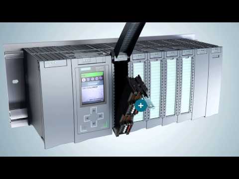
PLC Input Output Modules
caixiaofeng posted A plc and hmi english article in PLC programming learning
Every programmable logic controller must have some means of receiving and interpreting signals from real-world sensors such as switches, and encoders, and also be able to effect control over real-world control elements such as solenoids, valves, and motors. This is generally known as input/output, or I/O, capability. Monolithic (“brick”) PLCs have a fixed amount of I/O capability built into the unit, while modular (“rack”) PLCs use individual circuit board “cards” to provide customized I/O capability. PLC Input Output Modules The advantages of using replaceable I/O cards instead of a monolithic PLC design are numerous. First, and most obvious, is the fact that individual I/O cards may be easily replaced in the event of failure without having to replace the entire PLC. Specific I/O cards may be chosen for custom applications, biasing toward discrete cards for applications using many on/off inputs and outputs, or biasing toward analog cards for applications using many 4-20 mA and similar signals. Some PLCs even offer the feature of hot-swappable cards, meaning each card may be removed and a new one inserted without de-energizing power to the PLC processor and rack. Please note that one should not assume any system has hot-swappable cards, because if you attempt to change out a card “live” in a system without this feature, you run the risk of damaging the card and/or the rest of the unit it is plugged in to! Some PLCs have the ability to connect to processor-less remote racks filled with additional I/O cards or modules, thus providing a way to increase the number of I/O channels beyond the capacity of the base unit. The connection from host PLC to remote I/O racks usually takes the form of a special digital network, which may span a great physical distance: An alternative scheme for system expansion is to network multiple PLCs together, where each PLC has its own dedicated rack and processor. Through the use of communication instructions, one PLC may be programmed to read data from and/or write data to another PLC, effectively using the other PLC as an extension of its own I/O. Although this method is more expensive than remote I/O (where the remote racks lack their own dedicated processors), it provides the capability of stand-alone control in the event the network connection between PLC processors becomes severed. Input/output capability for programmable logic controllers comes in three basic varieties: discrete, analog, and network. -
Motor Trip Logic using PLC Programming
caixiaofeng posted A plc and hmi english article in PLC programming learning
Programmable Logic Controller (PLC) Questions and Answers This PLC is being used to start and stop an electric motor, and also to shut it down automatically if any of three “shutdown” conditions occur: Excessive vibration Overcurrent (overload heater contact) High winding temperature Motor Trip Logic using PLC Programming The status of each shutdown contact is as follows: Vibration contact: closed when okay, opens when vibration becomes excessive Overload contact: closed when okay, opens when overloaded Temperature contact: open when okay, closes when hot Draw a PLC ladder-logic program to start and stop this motor. Be sure to make the program latching so that the operator does not have to hold the Start button to keep the motor running. Answer: Do you find any mistakes in the logic? Share with us through comments. -
How to use PLC with SQL Database?
caixiaofeng posted A plc and hmi english article in PLC programming learning
In today’s world of industrial automation, data is a very important part. Getting instant data from sources and using them for different purposes is as crucial as running a system. Everyone usually knows how to integrate SCADA with various database systems, like SQL servers. However many ignore the power of PLC in integrating with databases. They too can be used for this purpose. PLC with SQL Database If we use PLC, programmers can work with them in emergency situations like SCADA failure and get their work done by coding it appropriately. In this post, we will see how to use PLC with SQL database. For those who are not familiar with SQL server, it is a database management tool which stores a large amount of data in real time format sequentially, and queries are written in it either through some external source, like a PLC, for retrieving data. For storing data in it, logic is written in PLC which when executed stores data in SQL. This is a simple concept, which is explained further in the post more briefly for it’s advantages. Scheduler PLC Suppose you have a very large-scale system where the operator has to feed hundreds of time schedules for operating particular functions every day. Instead of using vast coding and variables in PLC for storing data entered in SCADA and operating it once the time arrives, just feed all the variable data to the SQL server through PLC every time a new recipe is created. The SQL will store real-time date and time of the values entered and will give operators option of choosing them according to date and time filtered. For example, the SQL has five entries from 1st Oct to 5th Oct for various types of schedules entered. The benefit is that the operator can choose any one required and then run the system. If SQL was not there, he would have to run only one option of either 1st Oct or any other date. Or else, he would have to utilize memory of SCADA or PLC, which is waste of data and coding. This same thing becomes easier through SQL server. Another advantage is that SCADA code size becomes reduced and it would be used for other purposes. Scheduling is used in many applications and using PLC for it along with SQL makes system more efficient. Sequencing Consider a plant having 10 sequences. Every sequence has a barcode reader in it for starting the action on the required product. If the barcode is read in SCADA, then the corresponding data feed to PLC or in short, SCADA is the medial intervene for initiating communication between PLC and data; then just directly connect PLC with SQL. SQL will directly communicate with PLC for determining barcodes and other data for starting or stopping a sequence. Such bulk data from plant sequences helps reduce coding in SCADA and makes system faster to operate. Because PLC is written with coding for sequence operation, why not directly connect it with SQL and use the system. Synchronize multiple PLCs There are many applications where one PLC in a location needs data from another PLC location for doing a work. In that case too, traditionally SCADA is used for integrating all the PLC’s and managing them. In that case, if PLCs are directly connected to the SQL server, data will be synchronized through the date and time of SQL; thus, eliminating problems of multiple RTC (real-time clock) synchronization of PLCs. Also, PLC will directly communicate with other PLC for asking any data or give any data through the SQL server. Any alarm or event in a PLC will also be communicated to other PLC and would help in tracking real-time records. Handshaking Handshaking is a process where one party is acknowledged by the other party that the job has been completed. Basically, it is a response required so that the party can start its other work. This method works well with PLC and SQL servers. The SQL server can directly communicate with PLC by sending event notifications in real time, or alarm notification data in real-time. This means, suppose that the job has taken 3 days to complete. Then the completion acknowledgment will be sent as a separate event to the PLC, and as it also has 3 days of data in it, the operator can view the whole process in SCADA reports easily. So, handshaking is an important reason for communicating PLC with SQL directly. PLC Database Basics Establish a connection between the PLC and the SQL database using middleware or a gateway that facilitates communication between industrial network protocols and database languages. Select a communication protocol that both the PLC and the SQL database can understand, such as OPC UA, Modbus TCP, or any other protocol supported by your PLC and middleware. Configure the PLC to send and receive data by setting up the necessary parameters, registers, or tags that will be read from or written to. This might involve programming the PLC using its respective software to ensure it’s ready for data exchange. Set up the SQL database by creating a new database or configuring an existing one to store data from the PLC. Define tables, columns, and data types that align with the data structure being sent from the PLC. Map each PLC data point to the corresponding field in the SQL database. Ensure that the data types are compatible and that the mapping makes logical sense for the application’s needs. Implement data transfer logic using scripts or database stored procedures. Determine how often data should be transferred, under what conditions, and whether the transfer should be triggered by events or on a schedule. Test the communication between the PLC and the SQL database thoroughly. Check for any errors or data mismatches and ensure that the system behaves as expected under various conditions. Continuously monitor the system for operational integrity, data accuracy, and any anomalies. Set up alerts or notifications for system errors or significant events. Regularly review and update the system as needed to accommodate changes in the PLC setup, database structure, or additional requirements. Keep documentation updated for any system changes. Ensure security measures are in place for both the PLC and the SQL database to protect against unauthorized access and data breaches. Consider implementing encryption, firewalls, and secure access protocols. -
How to Troubleshoot Siemens PLC Programs?
xiangjinjiao posted A plc and hmi english article in PLC programming learning
This article is about the PLC programming troubleshooting method. In industrial PLCs where thousands of inputs and outputs are used, and we know how lengthy PLC programs are, depends on the application or plant usage. Troubleshoot Siemens PLC Programs Some times, People may change the logic parameters unknowingly and it may lead to a fault. Even some faults are created during the logic design stage due to the complexity of the design. The siemens plc software has different handy tools available in it to troubleshoot the faults generated in the programs. Faults can be like overlapping of addressing, multiple same output instances, memory bit address overlapping, many times a single program is used to work over and over, etc. To find out such problems, there are four types of windows available in the siemens software which will help us to troubleshoot the issues. They are: Cross Reference Call Structure Assignment List Dependency Structure Let discuss how to use them in our program for troubleshooting and where to find them in the software. Cross Reference Cross-reference is used to find all the digital & analog inputs and outputs used in the logics. It will help us to know about the number of times the I/O’s are used in the program and also take users directly to the specific location of the I/O’s in the logic pages. Here is an example of one of the programs, in which you can see how the cross-reference table looks like. It contains all the information like addressing, the language of the program, used inputs and outputs, etc. Call Structure When you want to know which block is used in programming then call structure is used. This is a reversal of cross-reference function in which we get to know that how many times SFC, FB block are used in OB (Organization Block) and here we get to know that how many times OB used in SFC and FBs. Assignment List The assignment list is a very useful feature when it comes to knowing that how many inputs, outputs, timers and counters used in our application and how many of them are still remaining, so we can use them in future logics. Dependency Structure Dependency structure is used to show where each and every block used within the programming. But in step 7 it won’t take you directly on location however in TIA PORTAL it will take you to the location where the program is written. NOTE: To open these windows in step 7, use the info as shown in Drawing. After clicking on display you have the options. In TIA PORTAL, follow the below step shown in the drawing. -
How to Troubleshoot a PLC System?
xiangjinjiao posted A plc and hmi english article in PLC programming learning
At this post i will give some basic instructions which are from my personal experience in order to give you a guide for how troubleshooting in automation systems (PLC/DCS) is : Automation systems troubleshooting has in general the same tactic in order to find the solution of system’s fault. Nevertheless, depends the complexity and the size of application and the specific automation system, the troubleshooting steps would be a little different or more complicated. The best knowledge is obtained through practice and actual troubleshooting conditions. Practice again and again is the solution in my opinion. Any supplement and comments are welcome!! Troubleshoot a PLC System Before we proceed, we agree that modern automation systems have PLCs for controlling the application. If we have a small application then the system possibly has a microPLC (or nanoPLC) or another type of compact controller (many times this depends of the application). I said modern automation systems because in the past (before PLCs/other compact controllers be well known and used by automation development companies), the control of an automation system was going on only with relays. Investigate the Controller’s program The first thing we should do, is to find out if we have the right conditions fulfilled for the operation that is faulty. To do this we should find the “mind” of our system. This “mind” is the controller (either this is a kind of PLC or another type of compact controller). If we don’t have the right conditions fulfilled, then we should investigate the controller’s programme for finding out the origin of the problem (ALWAYS check messages appear at SCADA.This will guide faster to the solution because at SCADA appear important information such as fault/alarm description or a specific address in PLC). The thing that we will find out is... either a faulty signal from hardware (eg a digital signal from a button or a digital signal from a mechanical switch or a digital signal from a relay’s contact that “does not come” to controller’s input or an analog signal which has wrong values) or a faulty signal from another software system (eg SCADA). Investigate the conditions that came from hardware When we conclude for the origin of the problem, then we leave for a while controller’s programme and go out to check our conclusions. We should already have find the drawings of automation system in order to see the connections for the components we want to check. For example, if we find out that we have a digital signal from a button which “does not come” to controller’s input, then we take our multimeter and go to check the button. If the button is OK, then we investigate if there is any fuse between button and controller’s input. If there is, then we check it. If the fuse is OK, then we investigate the route of the cable. Maybe we have a cut cable.If the cable is OK, then maybe we have hardware problem to the controller’s input and maybe we should change this input module with a new one or otherwise fix it (the repairs should be done by qualified staff). Investigate the hardware after the outputs of our controller If we conclude that we have the right conditions, then we should check the components that we have between controller and the faulty equipment (we mean the equipment that doesn’t work as it should). For example, if we have an industrial furnace that does not close its door (even though we have the conditions for closing the door from programme), maybe we have a faulty relay that energizes from PLC (or other controller) for closing the door. If the relay is OK, then maybe we have problem with the motor that is responsible for closing the door. We should check motor for its status (motor coils, mechanical parts) If the motor is OK, we should check the voltage values come to motor’s input (with our multimeter) and also check the cable for its status if multimeter’s measurements are not right. If the voltage and cable are OK, then maybe we have a jam somewhere at the door-furnace construction. Power units are a “plus”! Generally, when we have power units (drives) in our automation system in order to drive a motor, then we should have together the manual of the specific power unit. That’s because power units have a digital display or 7-segment led displays or simple LEd’s for informing us about the fault that exists inside them or at the driven motor. This is very useful for engineers and technicians. Also, modern power units have special algorithms for checking motor status, voltage and current values etc. For example, if a motor is overheated, the drive will inform us about it because it checks continuously the temperature sensor (eg thermistor) which is located inside motor’s enclosure. Then we should check the motor if it is overheated actually or we have a faulty temperature sensor that we should replace it. Check controllers status Some times, when the CPU of our PLC detects an unacceptable condition at the programme’s flow, then it goes to “STOP” mode and possibly a led flashes and indicates this malfunction. Also, if any other malfunction is going on to the system, some led’s indicate the kind of fault (refer to controller’s manual for more information). Same behavior have in general any kind of controller is established in an automation system. Safety systems Many automation systems (often production machines) have in their design some “safety systems” like “Pilz” or “Siemens Sirius”. These are smart compact controllers for monitoring situations like protective door opening or Emergency-Stop. When something of these occurs, the safety system stops the operation of the automation system for human and machine protection. In order to reset the automation system to the functional state, there are special instructions in safety systems manuals. The conclusion for all the above is to have a step by step tactic in troubleshooting. Passing time and getting more experience, maybe we will bypass some steps, specifically if we are the staff responsible for the maintenance of a system which we come across every day. However, a good tactic is to be organised and patient. Good luck to your efforts! -
How to filter analog and digital inputs in a PLC?
xiangjinjiao posted A plc and hmi english article in PLC programming learning
In this post, we will understand how to filter digital and analog inputs in a PLC. As the topic says, filtering is a means to remove unwanted spikes in the signals received in PLC. Its role is to eliminate the fluctuations and pass only proper signal changes at a particular time to the PLC. Inside a PLC, the filter circuitry comes first and then comes the PLC input processing circuitry, which accepts the final filtered input and uses it for its logic. PLC Digital Input Filters Let us first consider the digital input. The role of input with a filter is to accept a digital field input and pass it to a processing circuit through the filter. If you see the below image, there are two parts. First of all, the green circle indicates that the input change will be passed and the red circle shows that the input change will not be passed. In the first (above) part, there are two changes where there are many fluctuations and that input changes will be bypassed. There are two changes where there are no fluctuations and that input change will be passed to the processing circuit. The same is the theory with the second (below) part. This is possible by filtering. Filtering is defined by a factor or time. Suppose you set a time of 3 ms. The role of the filter is to accept only that input change that stays higher than 3 ms. If the input changes before 3 ms, then that input will not be considered and will be ignored. This means that short and high-frequency interference pulses will be neglected. This logic is the same as a debounce timer that we write in the PLC logic. In the below image, the lamp will turn on only when the start button input remains high for 3 seconds. This is the same logic used in a digital pass filter. It will pass on the input change to the processing part only when that input maintains a state (high or low) for the set time. Apart from time, as discussed, some PLCs have the option of setting a factor instead of time. The factor calculates the internal time and decides the level of filtering. Higher the factor value, the higher the filtering power. PLC Analog Input Filters Now, let us see the filtering in analog inputs. As analog inputs are variable in nature, the filter logic for them cannot be implemented the same as for digital inputs. So, in analog inputs, averaging logic is used. The filter will average the values attained in a particular set time and give an average final value for that time. Refer to the below image for the study. The first one – the blue color has a factor of 1. The second one – the green color has a factor of 2. The third one – the orange color has a factor of 3. The fourth one – the brown color has a factor of 4. As the value of the filter factor increases, you can see that the shape of the signal improves by filtering the signal at a sharper value. In a set time, the filter will average the values that it gets from the input; and based on formulas used inside it, it will give the final average output per time. So, as the filter factor or weightage is increased, we get a finer value of an analog signal with less interference. Normally, a first-pass filter is used for this purpose. In this way, we conclude that filtering is of great use in reducing unwanted noise from the field input and passing proper values, which will also protect the PLC input circuit from damage; if any high or unwanted spikes occur. -
DCS versus PLC Architecture
xiangjinjiao posted A plc and hmi english article in PLC programming learning
The main difference between DCS and PLC is the business model which we discussed with comparison of DCS Versus PLC Architecture. DCS versus PLC Architecture The DCS business model can be said to be based on a monolithic integrated system by a single manufacturer. DCS Architecture For a DCS the controller, I/O-subsystem, database server software, engineering software, and operator software are all a single monolithic unit designed together and only work with each other. It is not possible to use components from a third-party. It is not possible to use any of these components on some other system. A DCS uses I/O-subsystem network and control network based on standard Ethernet, but with a proprietary application protocol, and typically only with a particular approved model of Ethernet switches. Figure 1 In a DCS all components come from the same single manufacturer Only a specific version of Windows is permitted and only on one type of approved computer shipped from the DCS manufacturer. These restrictions enable the DCS manufacturer to test everything together very thoroughly, on a very large scale, heavily loaded, with many controllers and work stations. Applications like batch control, advanced control, and auto-tuning etc. are also tested together. This ensures there are no compatibility conflicts and unforeseen dependencies. Thorough large-scale testing is possible because there is essentially only one type of each component so only one or very few combinations. Third-party software is only permitted on separate “application stations” where it cannot conflict the native DCS applications and must be tested and approved by the DCS manufacturer; white-listed. A DCS is monolithic using the same brand I/O subsystem, controller, and software, and single computer and operating system platform. This has been thoroughly tested on very large scale. DCS Long Term Support Systems typically remain operational for 15 years or more. During this time there will be several Windows versions, service packs, hot fixes, lots of virus definition updates, and computer hardware will need to be replaced too. Typically DCS only support a single type of anti-virus software and whenever there is a new virus definition or when there is a Windows operating system service pack or hot fix, the entire monolithic suite of all hardware and software are tested together again by the system vendor prior to release ensuring the virus definition and service pack can be deployed without any compatibility conflicts. DCS Upgrade DCS versions are also upgraded as a single monolithic unit of all hardware and software such as I/O card firmware, controller firmware, server software, engineering station software, operator station software, as well as any other software are all upgraded together. Any time there is a new system version all these components have been thoroughly tested together on a large scale by the system manufacturer in advance ensuring they are all compatible with each other. Moreover, the online hotcutover process from earlier version to the new version has been thoroughly tested on a large scale ensuring smooth deployment at site. It is this reassurance that thorough and large-scale testing provides which makes DCS very popular with large installations like petrochemical complexes. Such testing is made practical by the few combinations in a monolithic system. PLC Architecture / Business Model The PLC business model can be said to be based on flexible architecture by a system integrator (SI). PLC Architecture The PLC architecture is very flexible where each component can be freely selected from any of many suppliers. The PLC is the CPU with configuration software and IO-subsystem. Sometimes the I/O-subsystem may come from a third-party. Even I/O cards that plug into the backplane may come from third-parties. The HMI software is typically from a third-party. A native OPC server from the PLC manufacturer is typically best, but third-party OPC servers are sometimes used. Figure 2 For a PLC components from different manufacturers are integrated Basically any PLC works with any I/O-subsystem, OPC server, and HMI software because standard protocols like PROFIBUS-DP, PROFINET, Modbus/RTU, Modbus/TCP, DeviceNet, and EtherNet/IP as well as OPC etc. are used. Networking gear, computers, and Windows version can be selected freely. Some components found not working are blacklisted. Figure 3 DCS uses a single supplier while PLC solutions combines multiple suppliers resulting in a large number of combinations Note: Now-a-days single PLC package supplier also available This flexibility enables hundreds of combinations of hardware and software making it impossible for these manufacturers to get together to test every possible combination of their hardware and software on each version of Windows before a plant decides to purchase. Some combinations may be tested by the manufacturers involved, but it may or may not be on large scale with heavy loading. A PLC permits any combination of I/O subsystem, CPU, and HMI/SCADA software, on a wide verity of computer and operating system platforms. Every combination cannot be tested. The PLC manufacturer may supply all hardware and software components, all from the same manufacturer as many PLC manufacturers have acquired HMI companies. If so, this particular combination may have been tested more thoroughly than the other combinations tested. Auxiliary third-party applications like batch control, advanced control, and auto-tuning etc. are generally not tested together as it results in an even greater number of combinations. PLC uses proprietary configuration software just like DCS. That is, you cannot use third-party configuration software for your PLC, just like a DCS. A native OPC server for the PLC is better than a third-party OPC server because the PLC configuration software generally automatically configures the address space for the OPC server. PLC Long Term Support During the 15 years or more of typical system operation there will be several Windows versions, service packs, hot fixes, lots of virus definition updates, and computer hardware will need to be replaced too. Typically PLC has no restriction on anti-virus software or Windows operating system version so again the number of combinations of virus definitions, service packs, and hot fixes becomes too vast and impractical for these manufacturers to get together to test every possible new combination before a deployment in plants to ensure there will be no compatibility conflicts when deployed on the large number of combinations of hardware and software. The PLC manufacturer may limit to a single anti-virus software and Windows version. If so, this particular combination may have been tested more thoroughly than the other combinations they test. PLC Upgrade For a PLC, hardware and software components are upgraded individually. That is, I/O-subsystem firmware, CPU firmware and configuration software, OPC server, HMI software, as well as any other software are all upgraded independent of each other. Taking different versions for each option of components into account, the number of combinations becomes orders of magnitude larger. This flexibility makes it impractical for these manufacturers to get together to test every possible combination of new versions before deployment in plants. Testing the hot-cutover of one combination of versions to another combination of versions becomes nearly impossible. The PLC manufacturer may supply all hardware and software components, limit to a single antivirus software and Windows version which are tested before deployment, and limit to single I/O-Subsystem Database Server Controller/PLC Operator Station / HMI, DCS, PLC system-wide version upgrades, and test hot-cutover before deployment. This way the flexibility of the PLC would be abandoned to achieve the robustness of a DCS. -
Control Algorithms in PLC Programming
xiangjinjiao posted A plc and hmi english article in PLC programming learning
When you are working in an industrial automation system for PLC programming, you have requirements where you need to control a process gradually or in a step-by-step way. Control Algorithms You cannot directly just on or off a logic for getting your work done. It can have adverse effects on your actual PLC output. For this reason, there are various types of control methods available in a PLC program for appropriate actions. In this post, we will see the various control algorithm methods that are used in a PLC program. PID control This is by far the most famous method for control. PID uses a closed-loop mechanism for control. This means it will first get the feedback and based on what you desire, it will accordingly vary the output. For this, PID controller uses internal mathematical calculations with three parameters – proportion, integral, and derivative. So, if you want to control a chiller with a compressor, then the PLC will control the compressor output by first measuring the actual temperature and checking it with how much the user requires. Based on that difference every time, the compressor output will either be controlled gradually or turned on-off to maintain the temperature. For this, a PID block will be used in the PLC program for doing this task. Function generator This is a very simple type of control method. In the function generator, you have to define an input table of n values. Similarly, define an output table of n values. So, for example, if we define 10 value tables in both the input and output sides, we have a 10-size element. Now, these 10 elements will have different values. If you set 0-100 on the input side, then we have set 0-50 on the output side. These 10 elements are 10 ranges, meaning 0-10, 10-20, 20-30, and so on. Accordingly, the output side will be distributed into 10 elements from 0-5, 5-10, 10-15 and so on till 50. When a real-time input is between any value at the input side, the corresponding scaled output will be passed. Here, you have full flexibility to set the input and output table values. Fuzzy logic control Fuzzy logic is a relatively very good method for controlling an output. Normally, you have two binary states – 0 and 1. So, let us consider whether a valve can be opened or closed. But what if the valve is stuck in between? We do not know whether the valve is near to open state or closed state. In that case, it helps if there exists a state between 0 and 1. This helps to at least come closer to a possibility. This is called fussy logic. Here, you get to define values near 0 and 1. It can be like 0.9 or 0.2. Accordingly, you can control the outputs when it comes close to these values. And when it reaches the extreme limit, that is 0 or 1, you can fully open or close the valve. Before that, you can gradually operate the valves. This brings more precise control to the process. So, this control block allows for a collection of values that can be useful in unpredictable situations. It requires a lot of knowledge and expertise to correctly set the values and sets so that the logic works properly. Position proportional This logic will open or close a device by pulsing open or close contacts at some predefined timer set by the user. It is done for a pulse width proportional to the deviation between the required position and the current position. You have to set control parameters like how much minimum and maximum to limit the output, what the duration for which output will remain on, the rate at which the device should open or close in %/second, etc. The function block takes actual feedback, evaluates internal timers, and checks whether the opening or closing is happening within that desired rate or not. If not, then the corresponding open or closed pulse will be given. In this way, we saw the various control algorithm methods used in PLC programming. -
Contacts and Coils in PLC Ladder Logic
xiangjinjiao posted A plc and hmi english article in PLC programming learning
The most elementary objects in Ladder Diagram programming are contacts and coils, intended to mimic the contacts and coils of electromechanical relays. Contacts and coils are discrete programming elements, dealing with Boolean (1 and 0; on and off; true and false) variable states. Each contact in a Ladder Diagram PLC program represents the reading of a single bit in memory, while each coil represents the writing of a single bit in memory. Discrete input signals to the PLC from real-world switches are read by a Ladder Diagram program by contacts referenced to those input channels. In legacy PLC systems, each discrete input channel has a specific address which must be applied to the contact(s) within that program. In modern PLC systems, each discrete input channel has a tag name created by the programmer which is applied to the contact(s) within the program. Similarly, discrete output channels – referenced by coil symbols in the Ladder Diagram – must also bear some form of address or tag name label. To illustrate, we will imagine the construction and programming of a redundant flame-sensing system to monitor the status of a burner flame using three sensors. The purpose of this system will be to indicate a “lit” burner if at least two out of the three sensors indicate flame. If only one sensor indicates flame (or if no sensors indicate flame), the system will declare the burner to be un-lit. The burner’s status will be visibly indicated by a lamp that human operators can readily see inside the control room area. Our system’s wiring is shown in the following diagram: Each flame sensor outputs a DC voltage signal indicating the detection of flame at the burner, either on (24 volts DC) or off (0 volts DC). These three discrete DC voltage signals are sensed by the first three channels of the PLC’s discrete input card. The indicator lamp is a 120 volt light bulb, and so must be powered by an AC discrete output card, shown here in the PLC’s last slot. To make the ladder program more readable, we will assign tag names (symbolic addresses) to each input and output bit in the PLC, describing its real-world device in an easily-interpreted format. We will tag the first three discrete input channels as IN sensor A, IN sensor B, and IN sensor C, and the output as OUT burner lit. A ladder program to determine if at least two out of the three sensors detect flame is shown here, with the tag names referencing each contact and coil: Series-connected contacts in a Ladder Diagram perform the logical AND function, while parallel contacts perform the logical OR function. Thus, this two-out-of-three flame-sensing program could be verbally described as: “Burner is lit if either A and B, or either B and C, or either A and C” An alternate way to express this is to use the notation of Boolean algebra, where multiplication represents the AND function and addition represents the OR function: Burner_lit = AB + BC + AC Yet another way to represent this logical relationship is to use logic gate symbols: To illustrate how this program would work, we will consider a case where flame sensors B and C detect flame, but sensor A does not (Note1). This represents a two-out-of-three-good condition, and so we would expect the PLC to turn on the “Burner lit” indicator light as programmed. From the perspective of the PLC’s rack, we would see the indicator LEDs for sensors B and C lit up on the discrete input card, as well as the indicator LED for the lamp’s output channel: Note 1 : The most likely reason why one out of two flame sensors might not detect the presence of a flame is some form of misalignment or fouling of the flame sensor. In fact, this is a good reason for using a 2-out-of-3 flame detection system rather than a simplex (1-out-of-1) detector scheme: to make the system more tolerant of occasional sensor problems without compromising burner safety. Those two energized input channels “set” bits (1 status) in the PLC’s memory representing the status of flame sensors B and C. Flame sensor A’s bit will be “clear” (0 status) because its corresponding input channel is de-energized. The fact that the output channel LED is energized (and the “Burner lit” indicator lamp is energized) tells us the PLC program has “set” that corresponding bit in the PLC’s output memory register to a “1” state. A display of input and output register bits shows the “set” and “reset” states for the PLC at this moment in time: Examining the Ladder Diagram program with status indication enabled, we see how only the middle contact pair is passing “virtual power” to the output coil: Recall that the purpose of a contact in a PLC program is to read the status of a bit in the PLC’s memory. These six “virtual contacts” read the three input bits corresponding to the three flame sensors. Each normally-open “contact” will “close” when its corresponding bit has a value of 1, and will “open” (go to its normal state) when its corresponding bit has a value of 0. Thus, we see here that the two contacts corresponding to sensor A appear without highlighting (representing no “conductivity” in the virtual relay circuit) because the bit for that input is reset (0). The two contacts corresponding to sensor B and the two contacts corresponding to sensor C all appear highlighted (representing “conductivity” in the virtual circuit) because their bits are both set (1). Recall also that the purpose of a coil in a PLC program is to write the status of a bit in the PLC’s memory. Here, the “energized” coil sets the bit for the PLC output 0 to a “1” state, thus activating the real-world output and sending electrical power to the “Burner lit” lamp. Note that the color highlighting does not indicate a virtual contact is conducting virtual power, but merely that it is able to conduct power. Color highlighting around a virtual coil, however, does indicate the presence of virtual “power” at that coil. Contacts and relays are not just useful for implementing simple logic functions, but they may also perform latching functions as well. A very common application of this in industrial PLC systems is a latching start/stop program for controlling electric motors by means of momentary-contact push-button switches. As before, this functionality will be illustrated by means of an hypothetical example circuit and program: In this system, two push-button switches are connected to discrete inputs on a PLC, and the PLC in turn energizes the coil of a motor contactor relay by means of one of its discrete outputs. An overload contact is wired directly in series with the contactor coil to provide motor over-current protection, even in the event of a PLC failure where the discrete output channel remains energized ( note 2 ). The ladder program for this motor control system would look like this: Note 2 : While it is possible to wire the overload contact to one of the PLC’s discrete input channels and then program a virtual overload contact in series with the output coil to stop the motor in the event of a thermal overload, this strategy would rely on the PLC to perform a safety function which is probably better performed by hard-wired circuitry. Pressing the “Start” pushbutton energizes discrete input channel 6 on the PLC, which “closes” the virtual contact in the PLC program labeled IN switch Start. The normally-closed virtual contact for input channel 7 (the “Stop” pushbutton) is already closed by default when the “Stop” button is not being pressed, and so the virtual coil will receive “power” when the “Start” pushbutton is pressed and the “Stop” pushbutton is not. Note the seal-in contact bearing the exact same label as the coil: OUT contactor. At first it may seem strange to have both a contact and a coil in a PLC program labeled identically (Note 3 ), since contacts are most commonly associated with inputs and coils with outputs, but this makes perfect sense if you realize the true meaning of contacts and coils in a PLC program: as read and write operations on bits in the PLC’s memory. The coil labeled OUT contactor writes the status of that bit, while the contact labeled OUT contactor reads the status of that same bit. The purpose of this contact, of course, is to latch the motor in the “on” state after a human operator has released his or her finger from the “Start” pushbutton. Note 3 : A very common misconception among students first learning PLC Ladder Diagram programming is to always associate contacts with PLC inputs and coils with PLC outputs, thus it seems weird to have a contact bear the same label as an output. However, this is a false association. In reality, contacts and coils are read and write instructions, and thus it is possible to have the PLC read one of its own output bits as a part of some logic function. What would be truly strange is to label a coil with an input bit address or tag name, since the PLC is not electrically capable of setting the real-world energization status of any input channels. This programming technique is known as feedback, where an output variable of a function (in this case, the feedback variable is OUT contactor) is also an input to that same function. The path of feedback is implicit rather than explicit in Ladder Diagram programming, with the only indication of feedback being the common name shared by coil and contact. Other graphical programming languages (such as Function Block) have the ability to show feedback paths as connecting lines between function outputs and inputs, but this capacity does not exist in Ladder Diagram. A step-by-step sequence showing the operation and status of this simple program illustrates how the seal-in contact functions, through a start-up and shut-down cycle of the motor: This sequence helps illustrate the order of evaluation or scan order of a Ladder Diagram program. The PLC reads a Ladder Diagram from left to right, top to bottom, in the same general order as a human being reads sentences and paragraphs written in English. However, according to the IEC 61131-3 standard, a PLC program must evaluate (read) all inputs (contacts) to a function before determining the status of a function’s output (coil or coils). In other words, the PLC does not make any decision on how to set the state of a coil until all contacts providing power to that coil have been read. Once a coil’s status has been written to memory, any contacts bearing the same tag name will update with that status on subsequent rungs in the program. Step 5 in the previous sequence is particularly illustrative. When the human operator presses the “Stop” pushbutton, the input channel for IN switch Stop becomes activated, which “opens” the normally-closed virtual contact IN switch Stop. Upon the next scan of this program rung, the PLC evaluates all input contacts (IN switch Start, IN switch Stop, and OUT contactor) to check their status before deciding what status to write to the OUT contactor coil. Seeing that the IN switch Stop contact has been forced open by the activation of its respective discrete input channel, the PLC writes a “0” (or “False”) state to the OUT contactor coil. However, the OUT contactor feedback contact does not update until the next scan, which is why you still see it color-highlighted during step 5. A potential problem with this system as it is designed is that the human operator loses control of the motor in the event of an “open” wiring failure in either pushbutton switch circuit. For instance, if a wire fell off a screw contact for the “Start” pushbutton switch circuit, the motor could not be started if it was already stopped. Similarly, if a wire fell off a screw contact for the “Stop” pushbutton switch circuit, the motor could not be stopped if it was already running. In either case, a broken wire connection acts the same as the pushbutton switch’s “normal” status, which is to keep the motor in its present state. Some applications, this failure mode would not be a severe problem. Many applications, though, it is quite dangerous to have a running motor that cannot be stopped. For this reason, it is customary to design motor start/stop systems a bit differently from what has been shown here. In order to build a “fail-stop” motor control system with our PLC, we must first re-wire the pushbutton switch to use its normally-closed (NC) contact: This keeps discrete input channel 7 activated when the pushbutton is unpressed. When the operator presses the “Stop” pushbutton, the switch’s contact will be forced open, and input channel 7 will de-energize. If a wire happens to fall off a screw terminal in the “Stop” switch circuit, input channel 7 will de-energize just the same as if someone pressed the “Stop” pushbutton, which will automatically shut off the motor. In order for the PLC program to work properly with this new switch wiring, the virtual contact for IN switch Stop must be changed from a normally-closed (NC) to a normally-open (NO): As before, the IN switch Stop virtual contact is in the “closed” state when no one presses the “Stop” switch, enabling the motor to start any time the “Start” switch is pressed. Similarly, the IN switch Stop virtual contact will open any time someone presses the “Stop” switch, thus stopping virtual “power” from flowing to the OUT contactor coil. Although this is a very common way to build PLC-controlled motor start/stop systems – with an NC pushbutton switch and an NO “Stop” virtual contact – students new to PLC programming often find this logical reversal confusing. Perhaps the most common reason for this confusion is a mis-understanding of the “normal” concept for switch contacts, be they real or virtual. The IN switch Stop virtual contact is programmed to be normally-open (NO), but yet it is typically found in the closed state. Recall that the “normal” status of any switch is its status while in a resting condition of no stimulation, not necessarily its status while the process is in a “normal” operating mode. The “normally-open” virtual contact IN switch Stop is typically found in the closed state because its corresponding input channel is typically found energized, owing to the normally-closed pushbutton switch contact, which passes real electrical power to the input channel while no one presses the switch. Just because a switch is configured as normally-open does not necessarily mean it will be typically found in the open state! The status of any switch contact, whether real or virtual, is a function of its configuration (NO versus NC) and the stimulus applied to it. Another concern surrounding real-world wiring problems is what this system will do if the motor contactor coil circuit opens for any reason. An open circuit may develop as a result of a wire falling off a screw terminal, or it may occur because the thermal overload contact tripped open due to an over-temperature event. The problem with our motor start/stop system as designed is that it is not “aware” of the contactor’s real status. In other words, the PLC “thinks” the contactor will be energized any time discrete output channel 2 is energized, but that may not actually be the case if there is an open fault in the contactor’s coil circuit. This may lead to a dangerous condition if the open fault in the contactor’s coil circuit is later cleared. Imagine an operator pressing the “Start” switch but noticing the motor does not actually start. Wondering why this may be, he or she goes to look at the overload relay to see if it is tripped. If it is tripped, and the operator presses the “Reset” button on the overload assembly, the motor will immediately start because the PLC’s discrete output has remained energized all the time following the pressing of the “Start” switch. Having the motor start up as soon as the thermal overload is reset may come as a surprise to operations personnel, and this could be quite dangerous if anyone happens to be near the motor-powered machinery when it starts. What would be safer is a motor control system that refuses to “latch” on unless the contactor actually energizes when the “Start” switch is pressed. For this to be possible, the PLC must have some way of sensing the contactor’s status. In order to make the PLC “aware” of the contactor’s real status, we may connect the auxiliary switch contact to one of the unused discrete input channels on the PLC, like this: Now, the PLC is able to sense the real-time status of the contactor via input channel 5. We may modify the PLC program to recognize this status by assigning a new tag name to this input (IN contactor aux) and using a normally-open virtual contact of this name as the seal-in contact instead of the OUT contactor bit: Now, if the contactor fails to energize for any reason when the operator presses the “Start” switch, the PLC’s output will fail to latch when the “Start” switch is released. When the open fault in the contactor’s coil circuit is cleared, the motor will not immediately start up, but rather wait until the operator presses the “Start” switch again, which is a much safer operating characteristic than before. A special class of virtual “coil” used in PLC ladder programming that bears mentioning is the “latching” coil. These usually come in two forms: a set coil and a reset coil. Unlike a regular “output” coil that positively writes to a bit in the PLC’s memory with every scan of the program, “set” and “reset” coils only write to a bit in memory when energized by virtual power. Otherwise, the bit is allowed to retain its last value. A very simple motor start/stop program could be written with just two input contacts and two of these latching coils (both bearing the same tag name, writing to the same bit in memory): Note the use of a normally-open (NO) pushbutton switch contact (again!), with no auxiliary contact providing status indication of the contactor to the PLC. This is a very minimal program, shown for the strict purpose of illustrating the use of “set” and “reset” latching coils in Ladder Diagram PLC programming. “Set” and “Reset” coils ( Referred to as “Latch” and “Unlatch” coils ) are examples of what is known in the world of PLC programming as retentive instructions. A “retentive” instruction retains its value after being virtually “de-energized” in the Ladder Diagram “circuit.” A standard output coil is non-retentive, which means it does not “latch” when de-energized. The concept of retentive and non-retentive instructions will appear again as we explore PLC programming, especially in the area of timers. Ordinarily, we try to avoid multiple coils bearing the same label in a PLC Ladder Diagram program. With each coil representing a “write” instruction, multiple coils bearing the same name represents multiple “write” operations to the same bit in the PLC’s memory. Here, with latching coils, there is no conflict because each of the coils only writes to the OUT contactor bit when its respective contact is energized. So long as only one of the pushbutton switches is actuated at a time, there is no conflict between the identically-named coils. This raises the question: what would happen if both pushbutton switches were simultaneously pressed? What would happen if both “Set” and “Reset” coils were “energized” at the same time? The result is that the OUT contactor bit would first be “set” (written to a value of 1) then “reset” (written to a value of 0) in that order as the two rungs of the program were scanned from top to bottom. PLCs typically do not typically update their discrete I/O registers while scanning the Ladder Diagram program (this operation takes place either before or after each program scan), so the real discrete output channel status will be whatever the last write operation told it to be, in this case “reset” (0, or off). Even if the discrete output is not “confused” due to the conflicting write operations of the “Set” and “Reset” coils, other rungs of the program written between the “Set” and “Reset” rungs might be. Consider for example a case where there were other program rungs following the “Set” and “Reset” rungs reading the status of the OUT contactor bit for some purpose. Those other rungs would indeed become “confused” because they would see the OUT contactor bit in the “set” state while the actual discrete output of the PLC (and any rungs following the “Reset” rung) would see the OUT contactor bit in the “reset” state: Multiple (non-retentive) output coils with the same memory address are almost always a programming faux pax for this reason, but even retentive coils which are designed to be used in matched pairs can cause trouble if the implications of simultaneous energization are not anticipated. Multiple contacts with identical addresses are no problem whatsoever, because multiple “read” operations to the same bit in memory will never cause a conflict. The IEC 61131-3 PLC programming standard specifies transition-sensing contacts as well as the more customary “static” contacts. A transition-sensing contact will “actuate” only for a duration of one program scan, even if its corresponding bit remains active. Two types of transition-sensing Ladder Diagram contacts are defined in the IEC standard: one for positive transitions and another for negative transitions. The following example shows a wiring diagram, Ladder Diagram program, and a timing diagram demonstrating how each type of transition-sensing contact functions when stimulated by a real (electrical) input signal to a discrete channel: When the pushbutton switch is pressed and the discrete input energized, the first test lamp will blink “on” for exactly one scan of the PLC’s program, then return to its off state. The positive transition contact (with the letter “P” inside) activates the coil OUT test1 only during the scan it sees the status of IN test transition from “false” to “true,” even though the input remains energized for many scans after that transition. Conversely, when the pushbutton switch is released and the discrete input de-energizes, the second test lamp will blink “on” for exactly one scan of the PLC’s program then return to its off state. The negative-transition contact (with the letter “N” inside) activates the coil OUT test2 only during the scan it sees the status of IN test transition from “true” to “false,” even though the input remains de-energized for many scans after that transition: It should be noted that the duration of a single PLC program scan is typically very short: measured in milliseconds. If this program were actually tested in a real PLC, you would probably not be able to see either test lamp light up, since each pulse is so short-lived. Transitional contacts are typically used any time it is desired to execute an instruction just one time following a “triggering” event, as opposed to executing that instruction over and over again so long as the event status is maintained “true.” Contacts and coils represent only the most basic of instructions in the Ladder Diagram PLC programming language. -
Comparison Instructions in PLC Programming
xiangjinjiao posted A plc and hmi english article in PLC programming learning
Comparison instructions in PLC are used to test pairs of values to condition the logical continuity of a rung. Thus, comparison instructions would seldom, if ever, be the last instruction on a rung. Types of Comparison Instructions As an example, suppose a LES instruction is presented with two values. If the first value is less than the second, then the comparison instruction is true. Equal (EQU) Instruction Use the EQU instruction to test whether two values are equal. If source A and source B are equal, the instruction is logically true. If these values are not equal, the instruction is logically false. Source A must be an address. Source B can be either a program constant or an address. Values are stored in two’s complementary form. Not Equal (NEQ) Instruction Use the NEQ instruction to test whether two values are not equal. If source A and source B are not equal, the instruction is logically true. Source A must be an address. Source B can be either a program constant or an address. Values are stored in two’s complementary form. Less Than (LES) Instruction Use the LES instruction to test whether one value (source A) is less than another (source B). If source A is less than the value at source B, the instruction is logically true. Source A must be an address. Source B can be either a program constant or an address. Values are stored in two’s complementary form. Less Than or Equal (LEQ) Instruction Use the LEQ instruction to test whether one value (source A) is less than or equal to another (source B). If the value at source A is less than or equal to the value at source B, the instruction is logically true. Source A must be an address. Source B can be either a program constant or an address. Values are stored in two’s complementary form. Greater Than (GRT) Instruction Use the GRT instruction to test whether one value (source A) is greater than another (source B). If the value at source A is greater than the value at source B, the instruction is logically true. Greater Than Or Equal (GEQ) Instruction Use the GEQ instruction to test whether one value (source A) is greater than or equal to another (source B). If the value at source A is greater than or equal to the value at source B, the instruction is logically true. Masked Comparison for Equal (MEQ) Use the MEQ instruction to compare data at a source address with data at a compare address. The Use of this instruction allows portions of the data to be masked by a separate word. Source is the address of the value you want to compare. Mask is the address of the mask through which the instruction moves data. The mask can be a hexadecimal value. Compare is an integer value or the address of the reference. If the 16 bits of data at the source address are equal to the 16 bits of data at the compare address (less masked bits), the instruction is true. The instruction becomes false as soon as it detects a mismatch. Limit Test (LIM) Instruction Use the LIM instruction to test for values within or outside a specified range, depending on how you set the limits. The Low Limit, Test, and High Limit values can be word addresses or constants, restricted to the following combinations: If the Test parameter is a program constant, both the Low Limit and High Limit parameters must be word addresses. If the Test parameter is a word address, the Low Limit and High Limit parameters can be either a program constant or a word address. True/False Status of the LIM Instruction If the Low Limit has a value equal to or less than the High Limit, the instruction is true when the Test value is between the limits or is equal to either limit. If the Low Limit has a value greater than the High Limit, the instruction is false when the Test value is between the limits. -
Basics of PLC Programming
xiangjinjiao posted A plc and hmi english article in PLC programming learning
In the late 1960’s an American company named Bedford Associates released a computing device they called the MODICON. As an acronym, it meant Modular Digital Controller, and later became the name of a company division devoted to the design, manufacture, and sale of these special-purpose control computers. Other engineering firms developed their own versions of this device, and it eventually came to be known in non-proprietary terms as a PLC, or Programmable Logic Controller. PLC The purpose of a PLC was to directly replace electromechanical relays as logic elements, substituting instead a solid-state digital computer with a stored program, able to emulate the interconnection of many relays to perform certain logical tasks. A PLC has many “input” terminals, through which it interprets “high” and “low” logical states & Analog values from switches and sensors. It also has many output terminals, through which it outputs “high” and “low” signals to power lights, solenoids, contactors, small motors, and other devices lending themselves to on/off control and also analog output for controlling control valves, motor speed control etc. In an effort to make PLCs easy to program, their programming language was designed to resemble ladder logic diagrams. Thus, an engineer accustomed to reading ladder logic schematics would feel comfortable programming a PLC to perform the same control functions. PLC Programming The following illustration shows a simple PLC, as it might appear from a front view. Two screw terminals provide connection to power supply for powering the PLC’s internal circuitry, labeled L1 and L2. Six screw terminals on the left-hand side provide connection to input devices, each terminal representing a different input “channel” with its own “X” label. The lower-left screw terminal is a “Common” connection, which is generally connected to L2 (neutral) of the 120 VAC power source. Inside the PLC housing, connected between each input terminal and the Common terminal, is an opto-isolator device (Light-Emitting Diode) that provides an electrically isolated “high” logic signal to the computer’s circuitry (a photo-transistor interprets the LED’s light) when there is 120 VAC power applied between the respective input terminal and the Common terminal. An indicating LED on the front panel of the PLC gives visual indication of an “energized” input: Output signals are generated by the PLC’s computer circuitry activating a switching device (transistor, TRIAC, or even an electromechanical relay), connecting the “Source” terminal to any of the “Y-” labeled output terminals. The “Source” terminal, correspondingly, is usually connected to the L1 side of the 120 VAC power source. As with each input, an indicating LED on the front panel of the PLC gives visual indication of an “energized” output: In this way, the PLC is able to interface with real-world devices such as switches and solenoids. The actual logic of the control system is established inside the PLC by means of a computer program. This program dictates which output gets energized under which input conditions. Although the program itself appears to be a ladder logic diagram, with switch and relay symbols, there are no actual switch contacts or relay coils operating inside the PLC to create the logical relationships between input and output. These are imaginary contacts and coils, if you will. The program is entered and viewed via a personal computer connected to the PLC’s programming port. Consider the following circuit and PLC program: When the pushbutton switch is unactuated (unpressed), no power is sent to the X1 input of the PLC. Following the program, which shows a normally-open X1 contact in series with a Y1 coil, no “power” will be sent to the Y1 coil. Thus, the PLC’s Y1 output remains de-energized, and the indicator lamp connected to it remains dark. If the pushbutton switch is pressed, however, power will be sent to the PLC’s X1 input. Any and all X1 contacts appearing in the program will assume the actuated (non-normal) state, as though they were relay contacts actuated by the energizing of a relay coil named “X1”. In this case, energizing the X1 input will cause the normally-open X1 contact will “close,” sending “power” to the Y1 coil. When the Y1 coil of the program “energizes,” the real Y1 output will become energized, lighting up the lamp connected to it: It must be understood that the X1 contact, Y1 coil, connecting wires, and “power” appearing in the computer’s (engineering system where PLC software loaded) display are all virtual. They do not exist as real electrical components. They exist as commands in a computer program — a piece of software only — that just happens to resemble a real relay schematic diagram. Equally important to understand is that the computer used to display and edit the PLC’s program is not necessary for the PLC’s continued operation. Once a program has been loaded to the PLC from the computer, the computer may be unplugged from the PLC, and the PLC will continue to follow the programmed commands. I include the computer display in these illustrations for your sake only, in aiding to understand the relationship between real-life conditions (switch closure and lamp status) and the program’s status (“power” through virtual contacts and virtual coils). The true power and versatility of a PLC is revealed when we want to alter the behavior of a control system. Since the PLC is a programmable device, we can alter its behavior by changing the commands we give it, without having to reconfigure the electrical components connected to it. For example, suppose we wanted to make this switch-and-lamp circuit function in an inverted fashion: push the button to make the lamp turn off, and release it to make it turn on. The “hardware” solution would require that a normally-closed pushbutton switch be substituted for the normally-open switch currently in place. The “software” solution is much easier: just alter the program so that contact X1 is normally-closed rather than normally-open. In the following illustration, we have the altered system shown in the state where the pushbutton is unactuated (not being pressed): In this next illustration, the switch is shown actuated (pressed): One of the advantages of implementing logical control in software rather than in hardware is that input signals can be re-used as many times in the program as is necessary. For example, take the following circuit and program, designed to energize the lamp if at least two of the three pushbutton switches are simultaneously actuated: To build an equivalent circuit using electromechanical relays, three relays with two normally-open contacts each would have to be used, to provide two contacts per input switch. Using a PLC, however, we can program as many contacts as we wish for each “X” input without adding additional hardware, since each input and each output is nothing more than a single bit in the PLC’s digital memory (either 0 or 1), and can be recalled as many times as necessary. Furthermore, since each output in the PLC is nothing more than a bit in its memory as well, we can assign contacts in a PLC program “actuated” by an output (Y) status. Take for instance this next system, a motor start-stop control circuit: The pushbutton switch connected to input X1 serves as the “Start” switch, while the switch connected to input X2 serves as the “Stop.” Another contact in the program, named Y1, uses the output coil status as a seal-in contact, directly, so that the motor contactor will continue to be energized after the “Start” pushbutton switch is released. You can see the normally-closed contact X2 appear in a colored block, showing that it is in a closed (“electrically conducting”) state. If we were to press the “Start” button, input X1 would energize, thus “closing” the X1 contact in the program, sending “power” to the Y1 “coil,” energizing the Y1 output and applying 120 volt AC power to the real motor contactor coil. The parallel Y1 contact will also “close,” thus latching the “circuit” in an energized state: Now, if we release the “Start” pushbutton, the normally-open X1 “contact” will return to its “open” state, but the motor will continue to run because the Y1 seal-in “contact” continues to provide “continuity” to “power” coil Y1, thus keeping the Y1 output energized: To stop the motor, we must momentarily press the “Stop” pushbutton, which will energize the X2 input and “open” the normally-closed “contact,” breaking continuity to the Y1 “coil:” When the “Stop” pushbutton is released, input X2 will de-energize, returning “contact” X2 to its normal, “closed” state. The motor, however, will not start again until the “Start” pushbutton is actuated, because the “seal-in” of Y1 has been lost: An important point to make here is that fail-safe design is just as important in PLC-controlled systems as it is in electromechanical relay-controlled systems. One should always consider the effects of failed (open) wiring on the device or devices being controlled. In this motor control circuit example, we have a problem: if the input wiring for X2 (the “Stop” switch) were to fail open, there would be no way to stop the motor! The solution to this problem is a reversal of logic between the X2 “contact” inside the PLC program and the actual “Stop” pushbutton switch: When the normally-closed “Stop” pushbutton switch is unactuated (not pressed), the PLC’s X2 input will be energized, thus “closing” the X2 “contact” inside the program. This allows the motor to be started when input X1 is energized, and allows it to continue to run when the “Start” pushbutton is no longer pressed. When the “Stop” pushbutton is actuated, input X2 will de-energize, thus “opening” the X2 “contact” inside the PLC program and shutting off the motor. So, we see there is no operational difference between this new design and the previous design. However, if the input wiring on input X2 were to fail open, X2 input would de-energize in the same manner as when the “Stop” pushbutton is pressed. The result, then, for a wiring failure on the X2 input is that the motor will immediately shut off. This is a safer design than the one previously shown, where a “Stop” switch wiring failure would have resulted in an inability to turn off the motor. In addition to input (X) and output (Y) program elements, PLCs provide “internal” coils and contacts with no intrinsic connection to the outside world. These are used much the same as “control relays” (CR1, CR2, etc.) are used in standard relay circuits: to provide logic signal inversion when necessary. To demonstrate how one of these “internal” relays might be used, consider the following example circuit and program, designed to emulate the function of a three-input NAND gate. Since PLC program elements are typically designed by single letters, I will call the internal control relay “C1” rather than “CR1” as would be customary in a relay control circuit: In this circuit, the lamp will remain lit so long as any of the pushbuttons remain unactuated (unpressed). To make the lamp turn off, we will have to actuate (press) all three switches, like this: -
PLC Programming Learning - Ladder Diagram Basics
xiangjinjiao posted A plc and hmi english article in PLC programming learning
Basics of Ladder Diagram in PLC Programming Ladder logic was originally a written method to document the design and construction of relay racks as used in manufacturing and process control.Each device in the relay rack would be represented by a symbol on the ladder diagram with connections between those devices shown. In addition, other items external to the relay rack such as pumps, heaters, and so forth would also be shown on the ladder diagram. Ladder logic has evolved into a programming language that represents a program by a graphical diagram based on the circuit diagrams of relay logic hardware. Ladder logic is used to develop software for programmable logic controllers (PLCs) used in industrial control applications. The name is based on the observation that programs in this language resemble ladders, with two vertical rails and a series of horizontal rungs between them. While ladder diagrams were once the only available notation for recording programmable controller programs, today other forms are standardized in IEC 61131-3. Ladder logic is widely used to program PLCs, where sequential control of a process or manufacturing operation is required. Ladder logic is useful for simple but critical control systems. As programmable logic controllers became more sophisticated it has also been used in very complex automation systems. Often the ladder logic program is used in conjunction with an HMI program operating on a computer workstation. Example of a simple ladder logic program The language itself can be seen as a set of connections between logical checkers (contacts) and actuators (coils). If a path can be traced between the left side of the rung and the output, through asserted (true or “closed”) contacts, the rung is true and the output coil storage bit is asserted or true. If no path can be traced, then the output is false (0) and the “coil” by analogy to electromechanical relays is considered “de-energized”. Ladder logic has contacts that make or break circuits to control coils. Each coil or contact corresponds to the status of a single bit in the programmable controller’s memory. Unlike electromechanical relays, a ladder program can refer any number of times to the status of a single bit, equivalent to a relay with an indefinitely large number of contacts. So-called “contacts” may refer to physical (“hard”) inputs to the programmable controller from physical devices such as pushbuttons and limit switches via an integrated or external input module, or may represent the status of internal storage bits which may be generated elsewhere in the program. Each rung of ladder language typically has one coil at the far right. Some manufacturers may allow more than one output coil on a rung. —( )— A regular coil, energized whenever its rung is closed. —()— A “not” coil, energized whenever its rung is open. —[ ]— A regular contact, closed whenever its corresponding coil or an input which controls it is energized. —[]— A “not” contact, closed whenever its corresponding coil or an input which controls it is not energized. The “coil” (output of a rung) may represent a physical output which operates some device connected to the programmable controller, or may represent an internal storage bit for use elsewhere in the program. Logical AND ------[ ]--------------[ ]----------------( ) Key Switch 1 Key Switch 2 Door Motor The above realizes the function: Door Motor = Key Switch 1 AND Key Switch 2 This circuit shows two key switches that security guards might use to activate an electric motor on a bank vault door. When the normally open contacts of both switches close, electricity is able to flow to the motor which opens the door. Logical AND with NOT ------[ ]--------------[]----------------( ) Close Door Obstruction Door Motor The above realizes the function: Door Motor = Close door AND NOT(Obstruction). This circuit shows a pushbutton that closes a door, and an obstruction detector that senses if something is in the way of the closing door. When the normally open push button contact closes and the normally closed obstruction detector is closed (no obstruction detected), electricity is able to flow to the motor which closes the door. Logical OR --+-------[ ]-------+-----------------( ) | Exterior Unlock | Unlock | | +-------[ ]-------+ Interior Unlock The above realizes the function: Unlock = Interior Unlock OR Exterior Unlock This circuit shows the two things that can trigger a car’s power door locks. The remote receiver is always powered. The lock solenoid gets power when either set of contacts is closed. Industrial STOP/START In common industrial latching start/stop logic we have a “start” button to turn on a motor contactor, and a “stop” button to turn off the contactor. When the “start” button is pushed the input goes true, via the “stop” button NC contact. When the “run” input becomes true the seal-in “run” NO contact in parallel with the “start” NO contact will close maintaining the input logic true (latched or sealed-in). After the circuit is latched the “stop” button may be pushed causing its NC contact to open and consequently the input to go false. The “run” NO contact then opens and the circuit logic returns to its quiescent state. --+----[ ]--+----[]----( ) | start | stop run | | +----[ ]--+ run -------[ ]--------------( ) run motor The above realizes the function: run = ( start OR run ) AND ( NOT stop ) Note the use of parenthesis to group the logical OR function before evaluating the logical AND function (which has a higher order of operation priority). Also note the use of NOT to represent the “stop” NC contact logic. This latch configuration is a common idiom in ladder logic. In ladder logic it is referred to as seal-in logic. The key to understanding the latch is in recognizing that “start” switch is a momentary switch (once the user releases the button, the switch is open again). As soon as the “run” solenoid engages, it closes the “run” NO contact, which latches the solenoid on. The “start” switch opening up then has no effect. For safety reasons, an Emergency-Stop and/or Stop should be hardwired in series with the Start switch, and the relay logic should reflect this. --[]----[]----+--[ ]--+---------( ) ES Stop | Start | Motor | | +--[ ]--+ Run Complex logic Here is an example of what two rungs in a ladder logic program might look like. In real world applications, there may be hundreds or thousands of rungs. Typically, complex ladder logic is ‘read’ left to right and top to bottom. As each of the lines (or rungs) are evaluated the output coil of a rung may feed into the next stage of the ladder as an input. In a complex system there will be many “rungs” on a ladder, which are numbered in order of evaluation. 1. ----[ ]---------+----[ ]-----+----( ) Switch | HiTemp | A/C | | +----[ ]-----+ Humid 2. ----[ ]----[]--------------------( ) A/C Heat Cooling Line 1 realizes the function: A/C = Switch AND ( HiTemp OR Humid ) Line 2 realizes the function: Cooling = A/C AND ( NOT Heat ) This represents a slightly more complex system for rung 2. After the first line has been evaluated, the output coil “A/C” is fed into rung 2, which is then evaluated and the output coil “Cooling” could be fed into an output device “Compressor” or into rung 3 on the ladder. This system allows very complex logic designs to be broken down and evaluated. Additional functionality Additional functionality can be added to a ladder logic implementation by the PLC manufacturer as a special block. When the special block is powered, it executes code on predetermined arguments. These arguments may be displayed within the special block. +-------+ -----[ ]--------------------+ A +---- Remote Unlock +-------+ Remote Counter +-------+ -----[ ]--------------------+ B +---- Interior Unlock +-------+ Interior Counter +--------+ --------------------+ A + B +----------- | into C | +--------+ Adder In this example, the system will count the number of times that the interior and remote unlock buttons are pressed. This information will be stored in memory locations A and B. Memory location C will hold the total number of times that the door has been unlocked electronically. PLCs have many types of special blocks. They include timers, arithmetic operators and comparisons, table lookups, text processing, PID control, and filtering functions. More powerful PLCs can operate on a group of internal memory locations and execute an operation on a range of addresses, for example, to simulate a physical sequential drum controller or a finite state machine. In some cases, users can define their own special blocks, which effectively are subroutines or macros. The large library of special blocks along with high speed execution has allowed use of PLCs to implement very complex automation systems. -
PLC programming for defective part classification
xiangjinjiao posted A plc and hmi english article in PLC programming learning
Advanced PLC programming for defective parts sorting to distinguish between good and bad parts and then transport them via conveyors. Advanced PLC Programming for Defective Parts Sorting The below simulation shows the good and bad products identification and sorting the products based on their quality using PLC ladder logic. The conveyors are used to move the products. The conveyors are started and stopped when the products are delivered on the conveyor and during the drilling operation. The drill machine is used for drilling the products as per the design. Sometimes the drilling operation may damage the products. A sensor detects the quality of the products and a pusher is used to push the bad products into another storage bin. PLC Inputs and Outputs The below table lists the required inputs and outputs of the PLC system. Type Device No. Device name Operation Input X0 Drilling ON while drilling. Input X1 Part under drill One part is supplied when Y0 is ON: A large metal cube. Input X2 Drilled correctly ON when the part is drilled correctly. The previous result is cleared when drilling starts. Input X3 Drilled wrong ON when the part is detected at the left end. Input X4 Sensor ON when the part is detected at the right end. Input X5 Sensor ON when the part is detected in front of the pusher. Input X10 Sensor ON when the part is not drilled correctly. The previous result is cleared when drilling starts. Output Y0 Supply command The conveyor moves forward when Y1 is ON. Output Y1 Conveyor forward The conveyor moves forward when Y3 is ON. Output Y2 Start drilling Starts drilling when Y2 is ON (A process cycle that cannot be stopped partway). Output Y3 Conveyor forward Extends when Y5 is ON and retracts when Y5 is OFF. The pusher cannot be stopped in the mid-stroke. Output Y5 Pusher Extends when Y5 is ON and retracts when Y5 is OFF. The pusher cannot be stopped in the mid stroke. Program Description This project aims to differentiate between good and defective parts using sensors and sorting them accordingly. The project consists of two key areas: overall control and drill control. Overall Control There is a pushbutton named PB1 (X20) on the control panel. When you press PB1, it triggers the Supply command (Y0) for the hopper, causing it to supply parts. Releasing PB1 deactivates the Supply command, stopping the hopper. There is a switch, SW1 (X24), on the control panel. When you turn SW1 ON, the conveyors start to move forward. Turning SW1 OFF halts the conveyors. Drill Control Now let’s discuss the control of the drill: When the Part under the drill sensor (X1) within the drill is activated, the conveyor halts. The drilling process commences when the Start drilling command (Y2) is activated. It stops when the Drilling sensor (X0) is activated. After one complete cycle of drill operation, if Start drilling (Y2) is activated, either the Drilled correctly (X2) or Drilled wrong (X3) sensor is triggered. Note that the drill can’t be stopped mid-operation. In this PLC simulation, every third part is considered defective (A part with multiple holes also falls into the defective category). When the Detect part sensor (X10) in the pusher identifies a defective part, the conveyor stops, and the pusher moves the part onto the ‘Defective’ tray. Remember that when the actuating command for the pusher is ON, it fully extends. When the command is OFF, the pusher fully retracts. A part that passes inspection continues along the conveyor to the ‘OK’ tray located at the right end. PLC Programming -

 Allen Bradley MicroLogix 1400 PLC :- • Capabilities for a maximum of 256 discrete I/O • Up to 6 embedded 100 kHz highspeed counters • 2 Serial ports • 1 Ethernet port • Built-in LCD to view controller and I/O status • Online Editing possible • Embedded Real Time Clock • Back-up Memory Module Asteam Techno Solutions Pvt. Ltd. was established in 2017 with a perspective to become a single-source supplier in Automation industry and is now regarded as one of the top Industrial Automation Parts Suppliers in India. Asteam Techno Solutions Pvt. Ltd. offer you the best products such as HMI, PLC, Power Supply, Servo Motor etc. that we sourced from the trusted brands like Allen Bradley, Siemens, Phoenix Contact, Moxa, Vipa and many more, which give you the maximum possible outcomes.
 -
English Siemens 西门子 SIMATIC S7-1500 系统布线 TOP 连接 UDOU_YmGLnE
leiwenge posted a video in Siemens PLC video
Siemens 西门子 SIMATIC S7-1500 系统布线 TOP 连接 UDOU_YmGLnE